
DMX

How to set up DMX controlled CLS fixtures?

To make DMX work correctly with CLS fixtures, we’ve put together some important information to keep in mind when you’re going to install your fixtures. Think about how to set an address, splitter cables, terminators and how to use your rail and DMX together.Ā 

max. 32

Fixtures per DMX line

0-512

Assignable addresses

Magnet

Required for addressing

3x

Fixture flickers = success

before you start

> WHAT TO KEEP IN MIND BEFORE INSTALLING

To make DMX work correctly with CLS fixtures, there are a few important things to keep in mind. Think about how to set an address, splitter cables, terminators, and how to use your rail and DMX together.

Most CLS LED fixtures are compatible with both DMX512 and Wireless DMX. Each fixture can be addressed individually, allowing you to program an intensity value for each fixture that can be adjusted quickly at any time from a remote control system.

memory on board

CLS fixtures offerĀ memory on board functionality. A pre-programmed intensity value can be stored in the fixture’s internal memory module. It is therefore not required to provide a continuous DMX control signal to the fixtures. The fixture will hold its last programmed value even if the controller is disconnected.

what you need

To configure DMX-controlled CLS fixtures you need a DMX controller with a digital interface and a simple magnet. You can address any CLS DMX-controlled fixture with a magnet. Any magnet that is strong enough will work. You can check this by placing the magnet on the dot on the back of the fixture.

Note before you start: CLS fixtures are always programmed on channel 1 by default. If you want all your fixtures to operate in the same way, you do not need to address them. Simply wire them and they will all respond identically.

wiring the daisy chain

> CONNECTING YOUR DMX UNIVERSE STEP BY STEP

The daisy chain of your DMX universe is simple to set up. Follow these steps to wire and configure your CLS LED fixtures correctly:

1.

Connect power to your controller and all fixtures.

2.

On your first fixture, put the DMX data cable in the DMX IN.

3.

Start the daisy chain by putting a DMX cable in the DMX OUT on fixture 1, and in the DMX IN on fixture 2

4.

Continue this chain for a maximum of approximately 32 fixtures. Check the product manual for the recommended maximum for your specific fixture.

5.

Set your fixtures to DMX channel mode and set a start address.

6.

Program your fixtures using the set address and the number of faders needed to use all functions.

Please note:Ā Ā Always place a 120 Ohm terminator on the DMX IN of the last fixture in your chain. Without termination, signal reflections can cause flickering or unstable fixture behaviour, especially on longer cable runs.

assigning an address

> HOW TO GIVE A CLS FIXTURE ITS START ADDRESS

To assign a starting address to a CLS LED fixture, you need a DMX controller with a digital interface and a magnet. CLS fixtures have a dedicated spot on the housing marked with a sticker. It looks like a circle with a smaller circle within it. Always use this marked location for the magnet.

1.

Set channel 1 on your DMX controller to a data output value between 1–255 for addresses 1–255,
or channel 2 for a data output value between 256–512 for addresses 256–512.

2.

Choose the address you want the fixture to be set to (1–512).

3.

Hold the magnet to the indicated spot on the back of the fixture to confirm. The fixture will flicker 3 times when the address has been set correctly.

4.

If all LEDs flash 10 timesĀ something went wrong. Please try again. If the problem persists, contact your local CLS distributor.

Grouping fixtures:Ā To assign the same address to multiple fixtures simultaneously, confirm the same address on all fixtures you want to control as one group. All fixtures on the same address will respond identically to the same controller input.

Channels per fixture type

> HOW MANY CHANNELS DOES YOUR FIXTURE NEED?

In CLS fixtures, there are three main lighting options. To program these, you only need to look at the number of colours. A fixture with only white LEDs needs 1 channel. A fixture with 4 coloured LEDs needs 4 channels.

WHITE (w)
1 cHANNEL

Single white LED output. One channel controls intensity from 0 to 255.
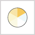
tUNABLE wHITE
2 CHANNELS

Two white channels (warm + cool). Adjust colour temperature and intensity independently.
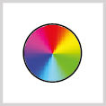
cOLOURfLOW rgbw / rgba
4 CHANNELS

One channel per colour: Red, Green, Blue, White (or Amber). Full colour mixing control.

Soft dim & master channel

If you choose to add theĀ Soft DimĀ option, you will need one extra channel. So with an RGBW fixture, you will need 5 channels to use all its options. If aĀ MasterĀ channel is also used, add another channel on top of that.

The Soft Dim and Master channel always comeĀ afterĀ the colour channels. So for a ColourFlow RGBW fixture: Soft Dim is channel 5 and Master is channel 6.

Please note: Always check the product manual. The programming table in the manual of each fixture shows the fixture-specific channel layout. For fixture-specific information, go to the product pages to download the manual.

For examples on how to address your installation without conflicts you can read more on
How does DMX work? – Address your installation without conflicts

full channel overview

> CHANNEL FUNCTIONS FOR CLS FIXTURES

The table below shows the function of every channel for CLS LED fixtures. Values marked with * are the default settings.

DMX

Function

Data

Parameters

Description

CH1

Set address

001 to 255

0

0 = no change*

Use this DMX channel to set an address from 001 to
255. The configured DMX address is called ā€œnā€

1…255

DMX address = 1…255

DMX

Function

Data

Parameters

Description

CH2

Set address

256 to 508

0

0 = no change

Use this DMX channel to set an address from 256 to 508. The configured DMX address is called ā€œnā€

Ā  1…255

DMX address = 256…508

DMX

Function

Data

Parameters

Description

Ā 

CH3

Ā 

Static

behaviour

0

no change

Ā 

If no DMX is present the fixture will respond like set in this function

1

Last DMX value*

2

Output off

3

Load static values

DMX

Function

Data

Parameters

Description

CH4

Soft dim

0

no change

When dynamic softdim is activated an extra DMX channel after the colours and/or master controls the soft dim reaction. If fixed no extra DMX channel is used.

1

off*

2

Dynamic

3-250

Fixed interpolation delay

DMX

Function

Data

Parameters

Description

Ā 

CH5

Ā 

Master

control

0

no change

If master is first channel is selected the channel will be DMX channel ā€œnā€. If master is last channel is selected the channel will be ā€œn+xā€

(ā€œxā€ is calculated in the output patch)

1

no master used*

2

master is first channel

3

master is last channel

Ā 

DMX

Function

Data

Parameters

Description

Ā 

CH6

Ā 

Output 1

patch

0

no change

Each output channel can be patched to respond to the

desired DMX channel. This enables the user to mix up the colours according to the controller that is used.

1

DMX channel n

2

DMX channel n+1

3

DMX channel n+2

4

DMX channel n+3

Example: all outputs are patched as 1

All outputs will be controlled by DMX channel “n”. If master is used total DMX channels will be 2, otherwise it uses 1 channel (“x” = 1).

Example: output 1&2 are patched as 1 and 3&4 are patched as 2

Output 1&2 will be controlled by DMX channel “n”.Ā 

Output 3&4 will be controlled by DMX channel “n+1”.Ā 

If master is used total DMX channels will be 3 otherwise it uses 2 channels (“x” = 2).

Ā 

DMX

Function

Data

Parameters

Description

Ā 

CH7

Ā 

Output 2

patch

0

no change

Ā 

Each output channel can be patched to respond to the desired DMX channel. This enables the user to mix up the colours according to the controller that is used.

1

DMX channel n

2

DMX channel n+1

3

DMX channel n+2

4

DMX channel n+3

Example: all outputs are patched as 1

All outputs will be controlled by DMX channel “n”. If master is used total DMX channels will be 2, otherwise it uses 1 channel (“x” = 1).

Example: output 1&2 are patched as 1 and 3&4 are patched as 2

Output 1&2 will be controlled by DMX channel “n”.Ā 

Output 3&4 will be controlled by DMX channel “n+1”.Ā 

If master is used total DMX channels will be 3 otherwise it uses 2 channels (“x” = 2).

DMX

Function

Data

Parameters

Description

Ā 

CH8

Ā 

Output 3

patch

0

no change

Ā 

Each output channel can be patched to respond to the desired DMX channel. This enables the user to mix up the colours according to the controller that is used.

1

DMX channel n

2

DMX channel n+1

3

DMX channel n+2

4

DMX channel n+3

Example: all outputs are patched as 1

All outputs will be controlled by DMX channel “n”. If master is used total DMX channels will be 2, otherwise it uses 1 channel (“x” = 1).

Example: output 1&2 are patched as 1 and 3&4 are patched as 2

Output 1&2 will be controlled by DMX channel “n”.Ā 

Output 3&4 will be controlled by DMX channel “n+1”.Ā 

If master is used total DMX channels will be 3 otherwise it uses 2 channels (“x” = 2).

Ā 

DMX

Function

Data

Parameters

Description

Ā 

CH9

Ā 

Output 4

patch

0

no change

Ā 

Each output channel can be patched to respond to the desired DMX channel. This enables the user to mix up the colours according to the controller that is used.

1

DMX channel n

2

DMX channel n+1

3

DMX channel n+2

4

DMX channel n+3

Example: all outputs are patched as 1

All outputs will be controlled by DMX channel “n”. If master is used total DMX channels will be 2, otherwise it uses 1 channel (“x” = 1).

Example: output 1&2 are patched as 1 and 3&4 are patched as 2

Output 1&2 will be controlled by DMX channel “n”.Ā 

Output 3&4 will be controlled by DMX channel “n+1”.Ā 

If master is used total DMX channels will be 3 otherwise it uses 2 channels (“x” = 2).

DMX

Function

Data

Parameters

Description

Ā 

Ā CH10

Ā 

Static output 1

0

no change

Each output channel can be set to a static intensity.

If no DMX is present and static behaviour is set to ā€œload static valuesā€. The outputs will be set to the configured intensity values.

1

Ā 

output off

2…255

intensity 2…255Ā  Ā  Ā *(255)

DMX

Function

Data

Parameters

Description

Ā 

Ā 

CH11

Ā 

Ā 

Static output 2

0

no change

Each output channel can be set to a static intensity.

If no DMX is present and static behaviour is set to ā€œload static valuesā€. The outputs will be set to the configured intensity values.

1

Ā 

output off

2…255

intensity 2…255Ā  Ā  Ā *(255)

DMX

Function

Data

Parameters

Description

Ā 

Ā CH12

Ā 

Static output 3

0

no change

Each output channel can be set to a static intensity.

If no DMX is present and static behaviour is set to ā€œload static valuesā€. The outputs will be set to the configured intensity values.

1

Ā 

output off

2…255

intensity 2…255

Ā 

Ā 

DMX

Function

Data

Parameters

Description

Ā 

Ā 

CH13

Ā 

Ā 

Static output 4

0

no change

Each output channel can be set to a static intensity.

If no DMX is present and static behaviour is set to ā€œload static valuesā€. The outputs will be set to the configured intensity values.

1

Ā 

output off

2…255

intensity 2…255Ā  Ā  Ā *(255)

DMX

Function

Data

Parameters

Description

CH14

Load default settings

0

no change

This function resets all settings to the Factory
setting. Check Factory settings.

1

Load Factory settings

Factory settings

Address

Static behaviour

Soft dim

Master control

Output patch 1

Output patch 2

Output patch 3

Output patch 4

Static output 1

Static output 2

Static output 3

Static output 4

1

1

Off

Off

1 (R)

2 (G)

3 (B)

4 (W)

255

255

255

255

Ā 

DMX

Function

Data

Parameters

Description


CH15


Input Resolution setting

0

no change

In 16 bit mode 2 channels are used per colour. First channel is rough channel, second channel fine. 16 bit mode is only available in DRIVE mode 2. 

1


8 bit*

2

16 bit

DMX ON TRACK SYSTEMS

> USING DMX WITH CLS TRACK FIXTURES - TROUBLE SHOOTING

When installing DMX-controlled fixtures on a CLS track system, the same addressing and programming rules apply. However, there are a few additional points specific to track installations to keep in mind.

connecting the ground wire

There is 1 common mistake when connecting the ground wire. We regularly hear that the fixtures on the rails do not work properly, flicker or contain many disturbances. This is often caused by a ‘ground wire loop’. The track is grounded on both sides, creating a loop. The ground on a DMX rail is 1-sided, so it only needs to be connected on 1 side.

maximum amount of fixtures on a rail

In general, it is recommended to connect a maximum of 32 fixtures to a DMX-Universe. In principle, this is no different for track, but to ensure that all fixtures perform optimally, we have looked at our recommended maximum number of fixtures on a rail. This number differs per fixture, and can be found in the manual of the product that will be installed.

inrush current

When all fixtures on a rail are switched on at the same time, the power supply receives a peak load. This peak can be more gradual by means of a current limiter. This limiter prevents your fuses from blowing out by curbing the current above a certain value.

Max. length track

In addition to a maximum number of recommended fixtures per track, there is also a maximum recommended length for the track itself. This is about 20M. This recommended length is for the data stream that runs through the track. The fixtures are sensitive to disturbances in a track because the data line is straight in it.Ā 

Note: couplers make the disturbances worse.Ā 

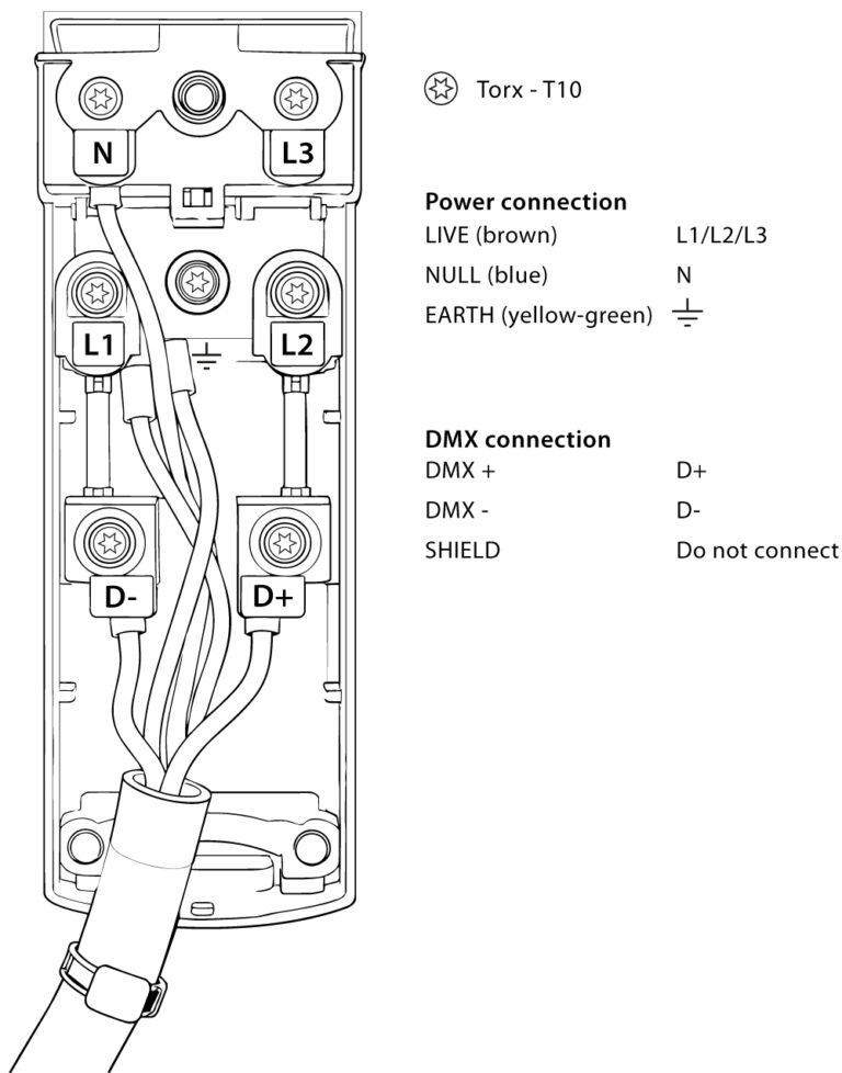
Global and data end feed

For proper connection of the global track, refer to the wiring diagram on the right. Depending on the group you intend to use, connect the live wire to L1, L2, or L3.

Global and data end feed

video explainer

> WATCH: HOW TO ADDRESS A DMX FIXTURE

View the video to see how to address DMX controlled fixtures. The PDF you can download below contains explanations to support addressing.

Continue reading

> RELATED ARTICLES

HOW DOES DMX WORK?

Learn what DMX is, how channels and addresses work, the difference between wired and wireless DMX, and when to use splitters and terminators.Ā 

LUMITAG - THE CLS NFC APP

Configure, diagnose and manage your CLS fixtures via NFC using the free LumiTaG app. No cables, no mains power, no complexity. Just hold your phone to the fixture.

stay up to date with our newsletter

> NEED ADVICE?

Want to know more about DMX? Look at our product pages to see which products are compatible with DMX, or contact us. We are happy to help. You can leave your question in the form below, and we will do our best to get back to you within 24 hours.

> Search our website